Media library

Media library

Find images, documents and videos that appear elsewhere on this site. Use the filters below to search by name, type or tag.

Image

wcm-pu-03corner.jpg
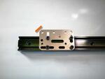
Orientation 1 (flat corner facing upper left)
wcm-pu-03corner.jpg
Orientation 1 (flat corner facing upper left
wcm-pu-03corner.jpg
wcm-pu-03corner.jpg
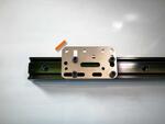
wcm-pu-06.jpg
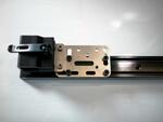
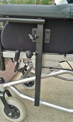
WB2 Mounted to a WC-AP4 - Orientation 1
wcm-pu-06.jpg
wcm-pu-06.jpg
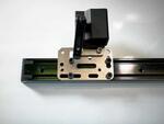
WB2 Mounted to a WC-AP4 - Orientation 2
wcm-pu-07.jpg
wcm-pu-07.jpg
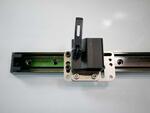
WB2 Mounted to a WC-AP4 - Orientation 3
wcm-pu-08.jpg
wcm-pu-08.jpg
wcm-pu-08.jpg
wcm-pu-08corner.jpg
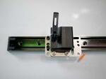
Orientation 2 (flat corner facing lower right)
wcm-pu-08corner.jpg
wcm-pu-08corner.jpg
wcm-pu-09corner.jpg
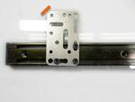
Orientation 3 (flat corner facing upper left)
wcm-pu-09corner.jpg
wcm-pu-09corner.jpg
wcm-pu2-01.jpg
wcm-pu2-01.jpg
wcm-pu2-01.jpg
wcm-pu2-02.jpg
wcm-pu2-02.jpg
wcm-pu2-03.jpg
wcm-pu2-03.jpg
wcm-pu2-04A.jpg
wcm-pu2-04A.jpg
wcm-pu2-04B.jpg
wcm-pu2-04B.jpg
wcm-pu2-04B.jpg
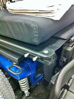
quantum slidetrack
wcm-quantum-slidetrack-TN.jpg
wcm-quickie-QM-710.jpg
wcm-rc-030-1.jpg
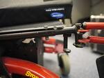
Older model Invacare TDX with round tubing
wcm-rc-030-1.jpg
wcm-rc-030-3.jpg
wcmq01-00.jpg
wcmq01-00.jpg
wcmq01-01.jpg
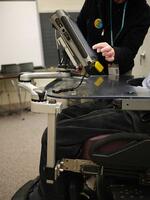
Mount'n Mover mounted
wcmq01-04.jpg
wcmq01-04.jpg
wcmq04-01.jpg
wcmq05-01.jpg
wcmq05-01.jpg
wcmq06-tn.jpg
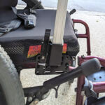
WC_AP4 attached to through holes in tubing
Approach 1: Sandwich the Sedeo Armrest bracket (on the right), using longer screws to attach an Adapter Plate.  Approach 2: Use two track nuts (see plate to the left) to attach an Adapter Plate.
WC_HC-Sedeo-Bracket.jpg
Attach an Adapter Plate 4 with two bolts through the slot in the armrest bracket. Orient the AP4 so the threaded holes are forward.
WC_LevoC3_1a-AP4.JPG
Use lock nuts or lock washers with a nut. Tighten securely.
WC_LevoC3_1b-AP4.JPG
Attach another plate, such as the L-Angle Extension Plate to locate the Wheelchair Bracket so it is to the side or front of the armrest.
WC_LevoC3_2a-LAE.JPG
This example shows the L-Angle Extension Plate attached lower, to offset the Solid Wheelchair Bracket so the mount can be positioned lower.
WC_LevoC3_2b-LAE.JPG
Attach the Solid Wheelchair Bracket L-Angle Extension Plate using the bolts and nuts supplied.
WC_LevoC3_3-WB2.JPG
WC_LevoC3_3-WB2.JPG
As you plan how you are attaching components, keep in mind you can orient them in different ways to offset them inward, forward and out. You can keep the post and mount in closer to the person, in front of the armrest to minimize the overall width.
WC_LevoC3_Complete.JPG
Place the post in the Wheelchair Bracket, attach the Mount and decide if you like the resulting position. Change the hardware if necessary. Review information on Offsets for more ideas.
WC_LevoC3_M2-attached.JPG
Attach the tray or device to make sure it is positioned where you need it. This photo shows the positioning in a seated position.
WC_LevoC3_sitting.JPG
As you can see, the mount and tray are in the same position relative to the person in a standing position. This is the benefit of attaching to a standing wheelchair's armrest where possible. The armrests on a standing wheelchair are typically more stable.
WC_LevoC3_standing.JPG
Attach the Adapter Plate 4 using 2 M8 bolts. The M8 bolts need to go through the larger holes and wider slot in the plate.
WC_MagMob-1_AP4.JPG
WC_MagMob-1_AP4.JPG
Attach an Angle Adjustment Plate to the threaded holes on the end of the AP4. You can flip the AAP either side to figure out the best two holes to align and attach the Solid Wheelchair bracket. You want the post to be as vertical as possible.
WC_MagMob-2_AAP.JPG
WC_MagMob-2_AAP.JPG
Next, attach the Solid Wheelchair Bracket to a set of threaded holes on the Angle Adjustment Plate, using the supplied bolts. Choose the set of holes that set the post close to vertical.
WC_MagMob-3_WB2.JPG
WC_MagMob-3_WB2.JPG
Insert the post, and attach the mounting arm.
WC_MagMob_attached.JPG
Move the device to a good operating position and set the lock positions on each joint.
WC_MagMob_M2.JPG
WC_MagMob_M2.JPG
Approach 1: Attach a Round clamp to the black tube just above the caster and behind the legrest. Approach 2: Attach using a Bridge Clamp on the base frame, just behind the caster; or attach a Bridge clamp to the side frame tube and the cross-frame tube.
WC_Orto-side.jpg
WC_Orto-side.jpg
WC_Orto-side2.jpg
WC_Orto-side2.jpg
Bottom of frame shows 3 possible attachment strategies: A bridge clamp on the side tubes just behind the caster; a bridge clamp on the side tube and cross-frame tube; or attaching to the vertical black tube just behind the legrest.
WC_Orto-under.jpg
WC_Orto-under.jpg
WC_OrtoBalance-attachR1.jpg
WC_SET-09_2017.jpg
Remove bolts holding tie-down
WC_Stingray-Step1.JPG
Attach the Wheelchair Bracket using the Angle Adjustment plate if necessary for a vertical post.
WC_StingrayOpt1.JPG
WC_StingrayOpt1.JPG
Attach the LAE using these holes
WC_StingrayOpt1_AP4-AddLAE.JPG
Another view of AP4 and LAE plates
WC_StingrayOpt1_AP4-LAE_side.JPG
Sandwich the Adapter Plate 4 between the Tie-down and frame, orienting the threaded holes to the side. Use longer bolts to reattach to compensate for added thickness of plate.
WC_StingrayOpt1_AP4.JPG
Attach Angle Adjustment plate to the LAE if necessary
WC_StingrayOpt2_AP4-LAE-AAP.JPG
Option #2: LAE attached to frame
WC_StingrayOpt2_Attached.JPG
Option #2: attach LAE to tiedown
WC_StingrayOpt2_LAE.JPG

Pages