Media library

Media library

Find images, documents and videos that appear elsewhere on this site. Use the filters below to search by name, type or tag.

Image
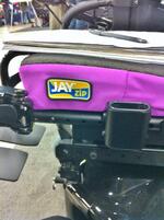
Attach through the holes in frame, using bolts and lock nuts to attach an Adapter Plate. Coved spacers optional.
QU-Pulse_holes.jpg
QU-Pulse_holes.jpg
QU-Q7.jpg
QU-Q7.jpg
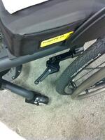
Brake off
QU-Q7_brakeOff.jpg
QU-Q7_brakeOff.jpg
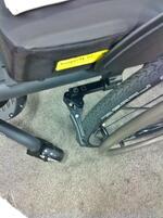
Brake on
QU-Q7_brakeOn.jpg
QU-Q7_brakeOn.jpg
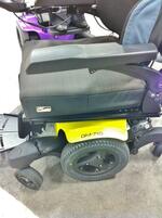
The QM710 has a dovetail slide track.
QU-QM710.jpg
QU-QM710.jpg
Slide two dovetail nuts in the slide track
QU-QM710_DovetailTrack.jpg
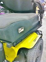
Dovetail slide track
QU-QM710_Track.jpg
QU-QM710_Track.jpg
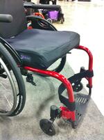
The QRI is attached to with either a bridge clamp, or by sandwiching an Adapter Plate between the Caster and the frame.
QU-QRI.jpg
QU-QRI.jpg
The sloping frame may require that you use an Angle Adjustment Plate to get the Wheelchair Bracket vertical.
QU-QRI_Front-Side.jpg
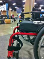
Side view
QU-QRI_Side.jpg
QU-QRI_Side.jpg
The top view gives a perspective as to the brake location.
QU-QRI_Top.jpg
QU-QRI_Top.jpg
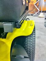
QU-QXi.jpg
QU-QXi.jpg
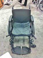
Note the brake handle position.
QU-QXi_front.jpg
QU-QXi_front.jpg
Attach using a Bridge Clamp, on the "J" and the vertical or horizontal tube section. Use an L-Angle to offset it and avoid interfering with brake actuation.
QU-QXi_Side.jpg
QU-QXi_Side.jpg
The Rhythm sometimes has round tube with thru holes
QU-Rhythm-Round.JPG
QU-Rhythm-Round.JPG
As needed, attach an L-Angle Extension plate to the AP4.  In this case, an AP2 was attached to the LAE.
QU-RR_AP4-LAE-AP2.JPG
AP4, LAE, WB2, and post
QU-RR_AP4-LAE-WB2-Post.JPG
Another option was to attach the WB2 to the LAE plate
QU-RR_AP4-LAE-WB2.JPG
Attach AP4 with long bolts and lock nuts
QU-RR_AP4.JPG
QU-RR_AP4.JPG
Mount'n Mover attached to a Maestro
QU-RR_Maestro-front.JPG
Mount'n Mover off to the side, for use when he pulls up to a table.
QU-RR_Maestro-side.JPG
The two bolts are either 5/16" or M8, so they must make use of the larger holes and slots on the Adapter Plate 4.  This means the Adapter Plate will be at an angle, so the Angle Adjustment plate will be needed.
QU-SU-AngleAP4_M8.JPG
AP4 plate
QU-SU-AngleAP4_M8.JPG
The Jive, with a Tie-down bracket on the seat frame.
QU-SU-Jive.JPG
QU-SU-Jive.JPG
QU-SU-Jive.JPG
The Salsa also has a Tie-down on its seat frame.
QU-SU-Salsa.JPG
QU-SU-Salsa.JPG
QU-SU-Salsa.JPG
The tie down has two bolts that go through the frame, with a nut on the opposite side.
QU-SU-TieDown.JPG
QU-SU-TieDown.JPG
Salsa tie down
QU-SU-TieDown.JPG
Notice the nut. The Adapter Plate can be sandwiched between the frame and the tie down, if the bolt is replaced with a longer one and lock nuts are used.
QU-SU_BoltsNuts.JPG
QU-SU_BoltsNuts.JPG
QU-SU_BoltsNuts.JPG
Attach using the tie-down holes or other holes in the tube as shown. Use offsets as needed.
QU-Z-RS.JPG
QU-Z-RS.JPG
QU-Z-Simba.JPG
QU-Z-Simba.JPG
Simba wheelchair with round tube frame--attach using a Bridge Clamp
QU-Z.JPG
QU-Z.JPG
Attach other components to offset Solid Wheelchair Bracket as needed. Adapter Plate 2, L-Angle Extension plates (2) shown.ame, AP2, LAE, WB2, and post.
QU-Zbop_AP-AP2-LAE-WB2-tray.jpg
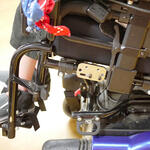
Attach the AP plate to the round tubing with holes. Use coved spacers (optional).
QU-Zbop_AP.jpg
QU-Zbop_AP.jpg
Mount'n Mover with eyegaze device and tray; required an offset forward and laterally.
QU-Zbop_M2-eyegaze-tray.JPG
Mount'n Mover with eyegaze device on Zippy Zone.
QU-Zone1_Eyegaze.JPG
An L-Angle Extension is shown attached to offset/reposition the Wheelchair Bracket.
QU-Zone1_OvalTC-AP4-LAE-WB2.JPG
Inside view
QU-Zone1_OvalTC-AP4-Post.JPG
Zippy Zone 1:  LAE plate is necessary to offset to avoid the brakes
QU-Zone1_OvalTC-AP4-WB2.JPG
A tight squeeze: an AP4 plate attaches to the Oval bridge clamps. Wheelchair Bracket is placed forward to allow brake use.
QU-Zone1_OvalTC-AP4.JPG
Inside view of bridge clamps and adapter plate attached to oval tube frame.
QU-Zone1_OvalTC-AP4_inside.JPG
QU-ZTS.jpg
Attach with bridge clamps on either side of the bend
QU-Z_close.JPG
QU-Z_close.JPG
The Quantum 6000 has a tie-down and slide track. You can attach using a tie-down sandwich or using a T-nut in the slide track.
Quantum 6000.jpg
Quantum Edge Stretto
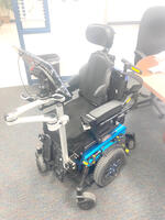
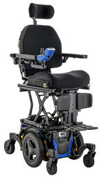
Quantum iLevel
Quantum iLevel
quantum ilevel
Quantum ilevel
Quantum ilevel
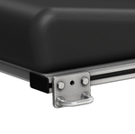
Quantum Tie-Down
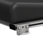
Quantum Tie-Down
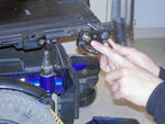
Quantum Tie-Down
Quantum Tie-Down
Remove the Quantum wheelchair tie-downs and replace the short bolt with the one supplied.
Quantum wheelchair tie-downs (removed in this picture)
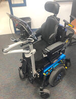
Quantum with T-nut_AP4_LAE_WB2
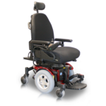
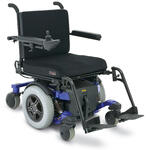
Quantum 600 has a slide track and a tie down.
Quantum-600-TCP-large.png
Quantum 610 has a slide track and a tie down.
Quantum-610-TCP-large.png
Quick Connect on Post.jpg
Quick Connect Plate.jpg
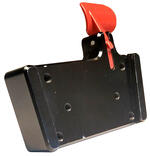
Quick Connect Receiver (QCR)
Quick Connect Receiver

Document

Quick Connect Receiver to DP-T2 portrait mode.pdf

Pages